Turning the Drivers, Part 4.
Finished with one pair of drivers, starting the next pair.
Since the support platform for the motor and reduction gear
was bolted to the concrete floor, moving to a different set of
drivers means moving the locomotive, with a fair amount of
takedown and setup involved. Back in part 1 of this series,
you saw the method of supporting an axle so it could be
elevated off the track. Now all those
steps must be reversed to permit moving the locomotive.
This page will show just a sample of those steps.
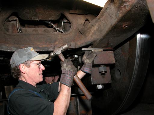
After the jacks have been lowered to set the drivers on
the track, the binders must be lowered a little so the spacer
blocks can be pulled out. Gravity being insufficient, Jim Vanderbeck
supplies some help with a wedge.
Photo by Terry Thompson.
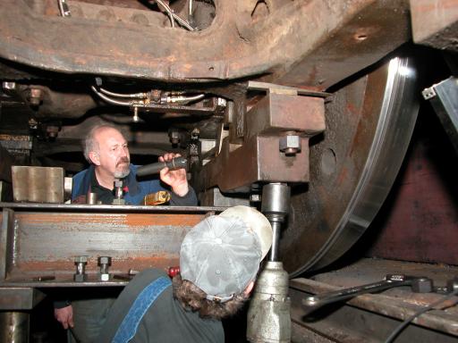
Jim backs off the nut while Tom Weisner watches for
clearance. The spacer block for the fireman's side
is out and sitting on the I-beam on the left edge of
the photo.
Photo by Terry Thompson.
Tom wiggles the heavy spacer block out over the edge
of the binder,
but setting it down on the I-beam will require Jim's help.
Photo by Terry Thompson.
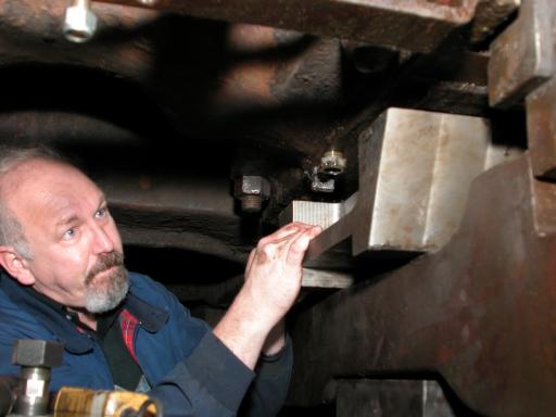
Tom prepares to begin removing the counter-counterweights from
the #2 driver on the engineer's side.
Overhead is a forklift boom that will do the lifting once the
weight is secured.
The #3 driver will require only a fraction of the weight.
Photo by Terry Thompson.
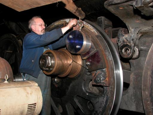
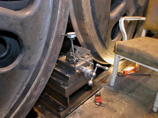
On the opposite side of the locomotive (firemans / left) side,
the driver on the left side of the photo is #3 and the right is
#4, which has already been turned. Tom begins work on #3 by assessing the
state of the wheel/tire combination with a dial indicator.
Photo by Terry Thompson.
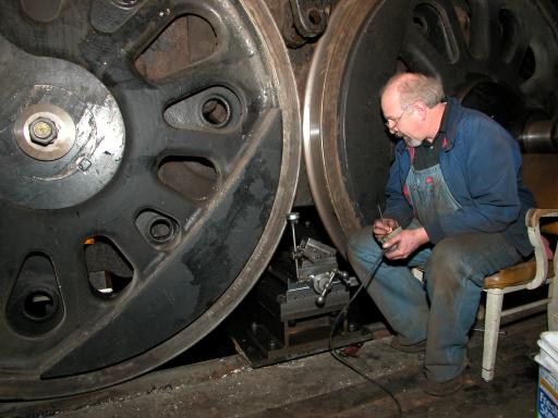
Tom controls the on/off switch for the motor so he can locate
the lateral extremes with the dial indicator.
Photo by Terry Thompson.
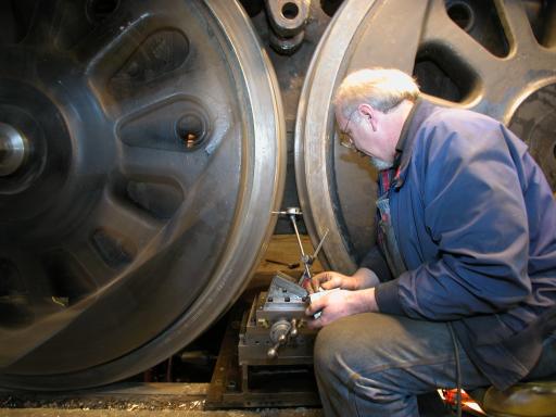
Determining the radial
extremes with the dial indicator.
Photo by Terry Thompson.
Turning the Drivers - Part 3
Return to Main Photo Gallery page
Return to Home page