Assembling the new valves
We call them new valves because everything is new except the spiders. All photos by Terry Thompson.
.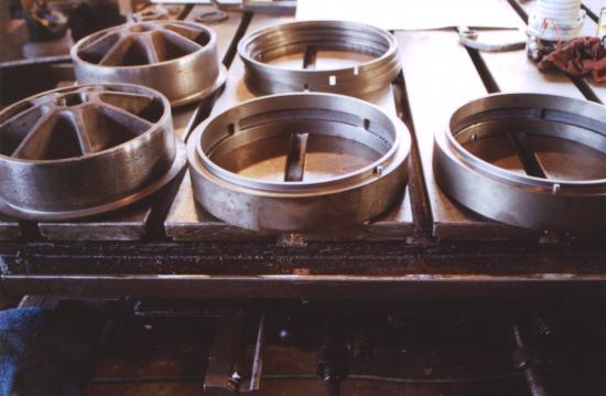
Some of the components. In the front row, a spider, and two bull rings. In the back, a spider and the piston rings (4) in a stack.
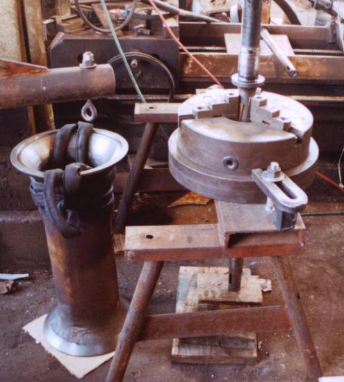
The valve shaft is held securely in a lathe chuck, ready for the other parts to be put in place. The end of the shaft on the floor is the end that will come out the rear of the valve cylinder and connect to the valve gear. The shoulder on the shaft just above the lathe chuck is a stop that the other components will be loaded against. The position of that shoulder is the beginning of the process of setting valve timing; all other measurements and adjustments will be made relative to it.
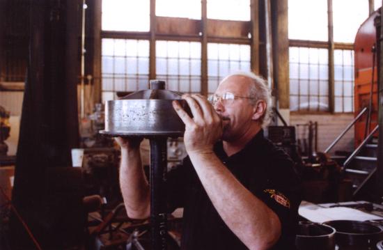
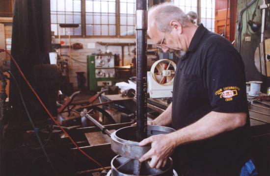
Machinist Tom Weisner places the first spider on the shaft.
Next is the outer piston ring.
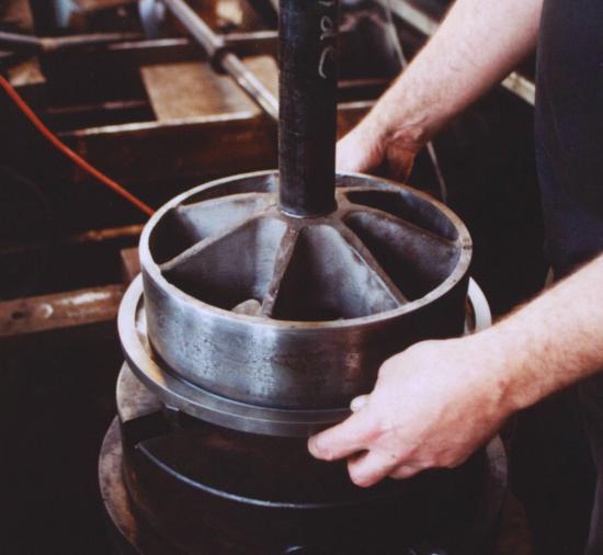
Now the bull ring.
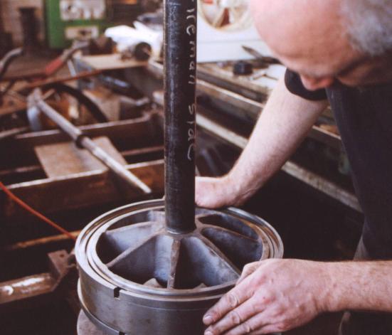
The inner piston ring is put in place as Tom aligns the gap on the anti-rotation pin..
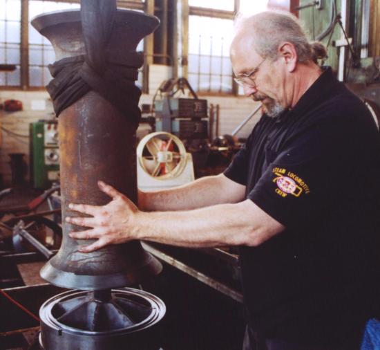
Tom slides the spool onto the shaft.
Inner piston ring for the other end of the valve.
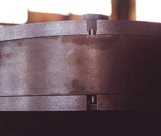
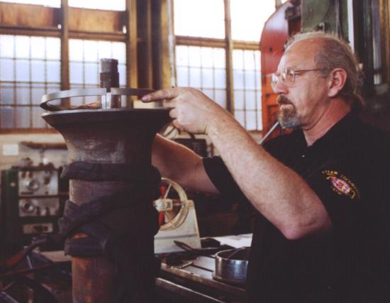
View of the ring gaps and the anti-rotation pins. If you visited a page showing the valve liners, remember the broadest bridge across the ports in the middle of the liner. The purpose of the anti-rotation pin is to locate the ring gap so that it travels across that bridge. That bridge sits at the bottom of the valve cylinder, incidentally.
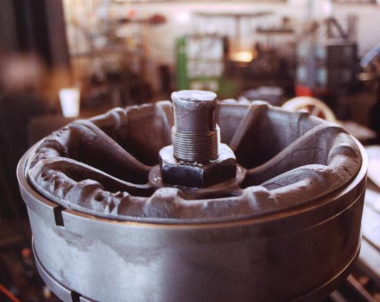
With the nut on, the only thing left to be put on is the wedge that goes in the slot near the end of the shaft. It's in the shaft shadow, unfortunately, so if you can't see it, just imagine it.
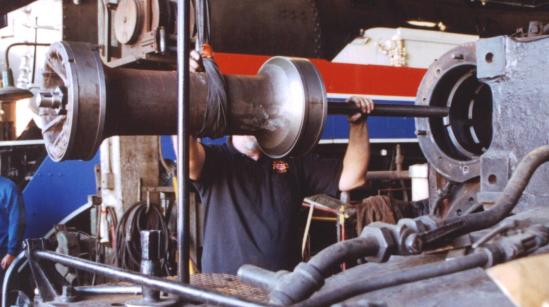
With the ladder removed and the feedwater pump not yet installed, Tom maneuvers the valve into the valve cylinder. Visible behind Tom in the next stall over is the SP 4449 in AFT paint scheme.