Gallery
SP&S 700 Boiler Rebuild and Inspection of 2000

The Federal Railroad Administration (FRA) requires a thorough periodic boiler inspection to ensure public safety.
The Federal Railroad Administration's updated rules for steam locomotives ("Steam Locomotive Inspection and Maintenance Standards," CFR49 Part 230) took effect January 18, 2000. Among other things, the new rules required a boiler cleaning and inspection every fifteen years or 1472 service days (when "the locomotive has steam pressure above atmospheric pressure and a fire in the firebox"), whichever comes first. The inspection must include a meticulous examination of every rivet, plate, and seam of the boiler shell as well as an ultrasonic thickness survey of the firebox and boiler. Such a thorough inspection requires that all the superheaters and flue tubes be removed from the boiler, which is a very big job. The SP&S 700 met nearly all of the new requirements, but still needed the boiler inspection in order to retain its FRA certification. The PRPA successfully completed the inspection in 2000 and early 2001. The steps of the project included:
- Pulling the Superheater Units
- Pulling the Boiler Flue Tubes
- Initial PRPA Boiler Assessment
- Sandblasting the Boiler
- Exterior Boiler Preparation
- Ultrasonic Testing
- More Cleaning and Fixing
- Swaging the New Tubes
- Stuffing the Flues
- Pressure Testing the Superheaters
- Putting Everything Back Together
QuickTime Tour THROUGH the SP&S 700
While the boiler work was well underway, Dale Birkholz took advantage of the unusual access to the innards of the engine in order to put together a full virtual tour. The tour leads the viewer from the pilot right through the boiler to the cab. There is no more thorough tour of the 700 than this and no better introduction to the work that goes into the 15-year inspection!
|
The tour starts outside the Brooklyn Roundhouse, where the 700 was maintained in those days. A full outline of the tour is below, and some tips to help you navigate are on the right. |
Primer on how to navigate:
|
| Description | Scene Type | Hotspots | |
|---|---|---|---|
| 1. | Brooklyn roundhouse sign | Still | Sign and door lead to #2 |
| 2. | Pile of boiler flues | Still | Roundhouse door leads to #3 |
| 3. | Carrying boiler tube down from the smokebox | Still | Smokebox door leads to #4 |
| 4. | View inside the smokebox | 360 | Upper right part of front tube sheet leads to #5 |
| 5. | The superheater manifold seen from the smokebox | Still | Upper right part of front tube sheet leads to #6 |
| 6. | View inside the boiler | 360 | Dry pipe leads to #6.1.1 Top of rear sheet plate leads to 6.2 Bottom of rear sheet plate leads to #7 |
| 6.1.1. Dry pipe shutoff valve | Still | Valve leads to #6.1.2 | |
| View thru steam dome | Still | Hole for steam dome leads back to #6 | |
| 6.2. Crown sheet stay bolts | Still | Crown stays lead back to #6 | |
| 7. | View inside the firebox | 360 | Red dye penetrant leads to #7.1.1 Firebox door leads to #8 |
| 7.1.1. Closer view spraying dye | Still | Dye leads to #7.1.2 | |
| 7.1.2. Still closer view of dye | Still | Dye leads back to #7 | |
| 8. | View in the cab | 360 | Exiting fireman's side leads back to #1 |
NOTE: If you're having trouble viewing the tour, you may need to download the QuickTime plug-in for your browser from Apple Computer. The file is 1.2MB, so it may also just take a little bit more patience to get it loaded, depending on your internet connection speed.
I. Pulling the Superheater Units
Jan 2000: To get to the boiler you have to remove the flue tubes. To remove the tubes you first need to pull out the superheaters. Let's get started!
1. Smokebox Ready for Work: The smokebox has been cleaned and the petticoat, nozzle, baffles, and blower have been removed. Photo by Terry Thompson. 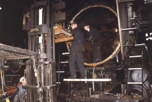
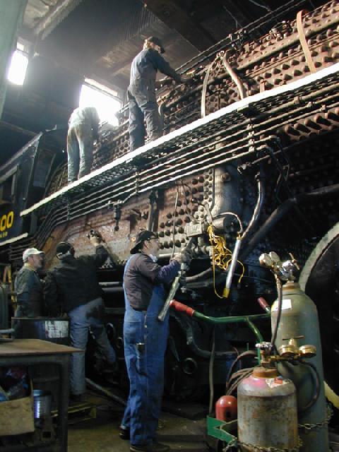
3. Pulling the Superheater Units: Using the 4449 crew's forklift and a custom cradle they made, we pull the units out with a come-along into the cradle. Then the forklift lays them down outside where we are stacking them. Working here are Jim Vanderbeck, who just got off the forklift, Matt Baccitich, and David Thompson in the smokebox. Photo by Terry Thompson. 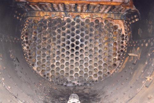
5. Front Tube Sheet Revealed: This is what it looks like in the smokebox with all the superheater units removed. Photo by Terry Thompson. |
2. Removing T-Bolts: Atop the smokebox, Matt Baccitich is removing nuts off the T-bolts that hold the superheaters tightly up against the sockets. Photo by Terry Thompson. 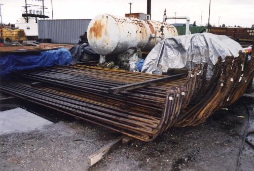
4. Piling up the Superheater Units: About 90% of the superheaters are out. If you wondered, these are Type E units. Photo by Terry Thompson. |
II. Pulling the Boiler Flue Tubes
A person can get in and out of the boiler pretty easily through the steam dome on the top of the locomotive. It's not so easy to get the boiler flues in and out. At either end, they are attached to the front and rear tube sheets. They have to be cut on the firebox end (welded) and notched on the smokebox end, then pounded through with a sledge hammer.
1. Notching Boiler Flues: Walt Eisenman in the smokebox notching the next several rows of flues to come out. Photo by Terry Thompson. 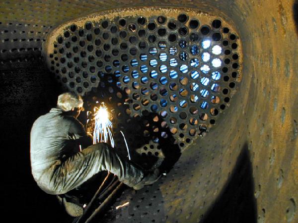
3. Cutting Flues: Walt Eisenman cutting a tube in the firebox (they are welded at this end) so it can be removed. Photo by Dale Birkholz. 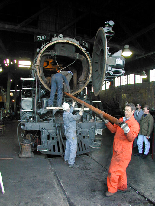
5. Pulling Flues Out of the Boiler: In the foreground are Steve Speer and Terry Thompson. On the pilot is David Thompson. In the smokebox are Bob Vanderbeck, John Rosu, and Jim Vanderbeck. Photo by Dale Birkholz. |
2. Close-up of Notched Flues: This picture shows how they are notched. Photo by Terry Thompson. 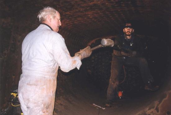
4. Sledging the Tubes through the Front Tube Sheet: To get the flues started out, they have to be driven from the firebox with a pipe against the cut end. Walt Eisenman (aka "John Henry") puts some beef into it while John Cox holds the pipe. Photo by Terry Thompson. 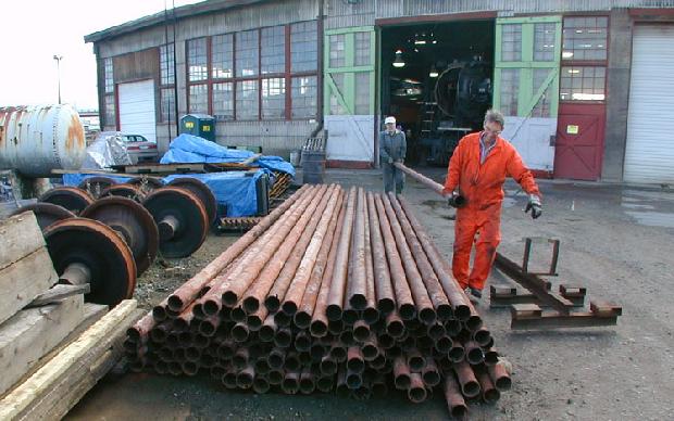
6. Piling up the Old Flues: Photo by Dale Birkholz. 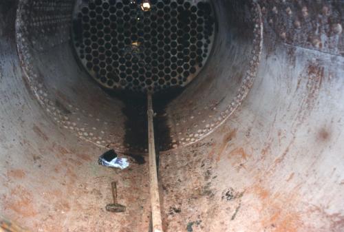
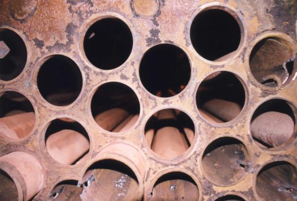
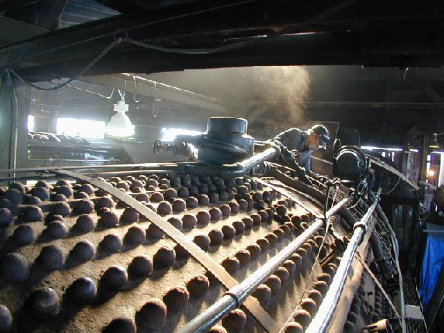
7. An Empty Boiler: Inside the boiler looking toward the smokebox. Photo by Terry Thompson. |
III. Initial PRPA Boiler Assessment
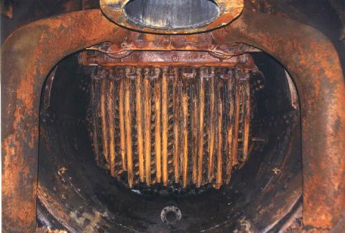
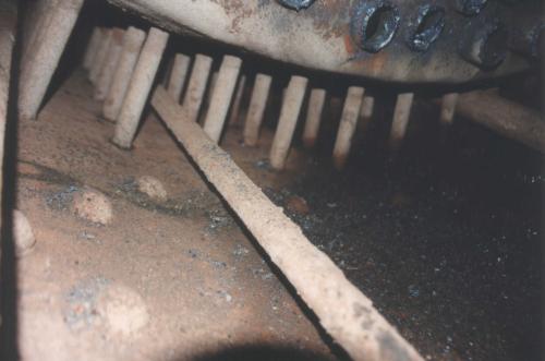
In late January, after removing the tubes, we took pictures of the boiler. These pictures were taken before any cleaning of the boiler. As you will see, this boiler is in great condition.
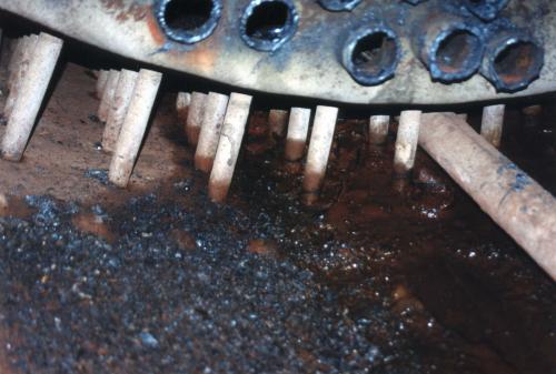
1. Staybolts on the Engineer's Side: The bluish debris in the foreground is from cutting off the tubes from the firebox tube sheet. Photo by Terry Thompson. 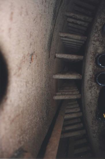
3. Staybolts on the Engineer's Side. Photo by Terry Thompson. 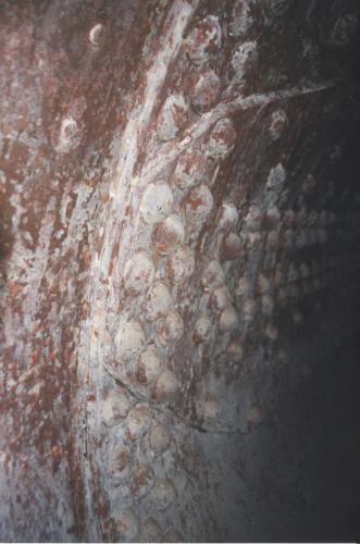
5. Close up of a Seam. Photo by Terry Thompson. |
2. Staybolts on the Engineer's Side. Photo by Terry Thompson. 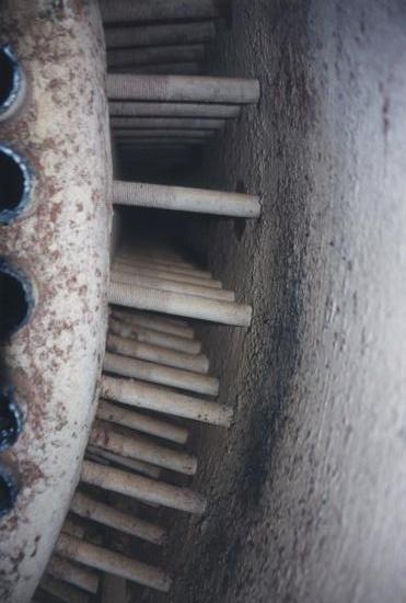
4. Looking at the Staybolts around the Combustion Chamber on the Fireman's Side. Photo by Terry Thompson. 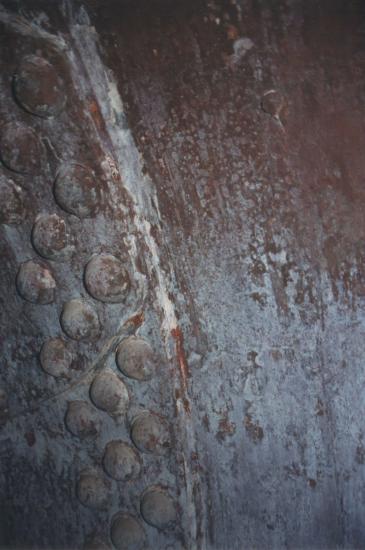
6. Close up of a Seam. Photo by Terry Thompson. |
IV. Sandblasting the Boiler
CCS Inc. sandblasted the boiler interior on February 26, 2000. They arrived at 6 am and were done by mid-afternoon. We paid for materials and they donated their time. A big thank you to CCS Inc. for a great job!
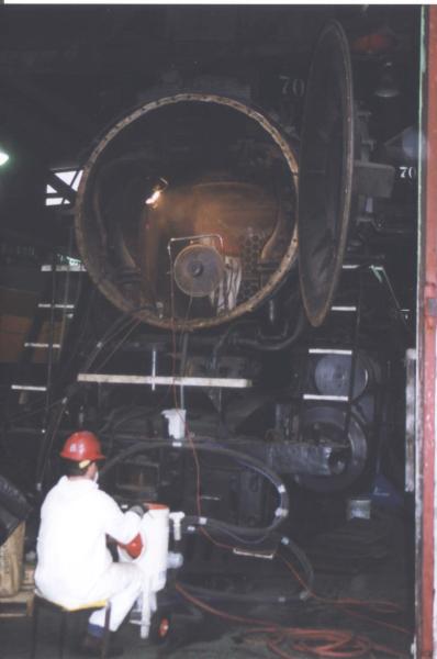
1. Sandblasting the Outside of the Front Tube Sheet: The CCS worker in the foreground rocks the canister to keep the sand flowing freely, while the guy in the smokebox operates the sandblaster. Photo by Terry Thompson. |
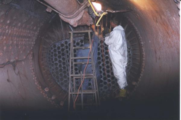
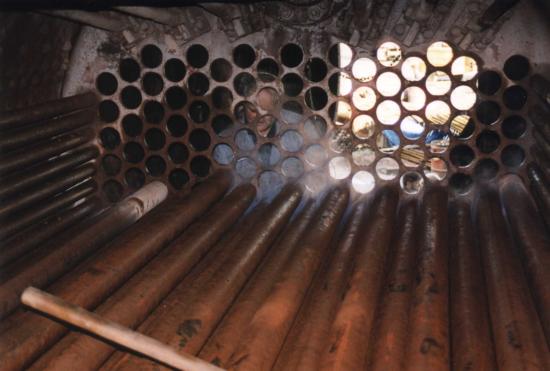
2. A Quick Inspection inside the Boiler: Sandblasting has progressed within the boiler. It's not a great time to have a camera or unprotected eyes nearby while they're working, but at a break in the action, they bring Walt Eisenman (our Chief Mechanical Officer at the time) in for a look-see. Photo by Terry Thompson. |
V. Exterior Boiler Preparation
With the interior of the boiler now cleared out and sandblasted clean, it is time to remove the jacketing and insulation and to clean up the outside of the boiler. Both sides of the boiler must be clean and bare to do the ultrasonic thickness measurements.
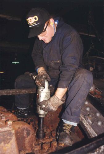
1. Wirebrushing the Staybolt Caps: Terry Thompson applies some elbow grease to get those caps clean so they can be inspected for cracks or damage. Photo by Dale Birkholz. 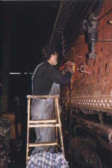
3. Cleaning a Measurement Spot: Ultrasonic thickness measurements can only be made on bare metal; paint or corrosion invalidates the reading. Here, Charlie Harrison smooths the spot on the grid to be measured. Photo by Terry Thompson. |
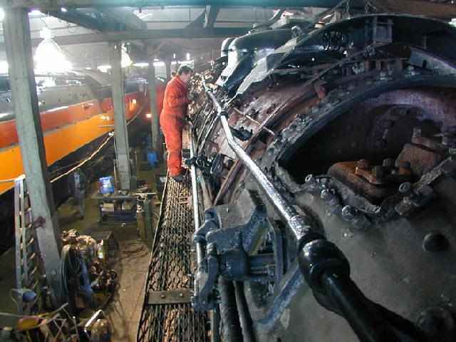
2. More Wirebrushing: Steve Speer wields the wirebrush further down the barrel of the boiler shell. Photo by Dale Birkholz 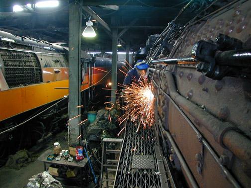
4. Another Measurement Spot: Jim Vanderbeck grinds clean another ultrasonic measurement location. SP 4449 stands at left with part of its jacketing removed too. Photo by Dale Birkholz. |
VI. Ultrasonic Testing of the Boiler
It is finally time to measure the thickness of the boiler shell. A handheld ultrasonic meter is used to make these measurements. The measurements are later used to calculate the boiler's maximum safe operating pressure using FRA's "Form 4," which will be scrutinized by an FRA mechanical engineer to ensure that the boiler is safe for operation.
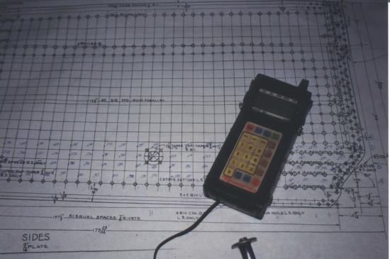
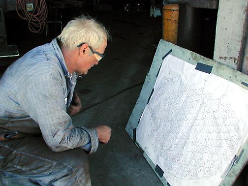
1. The Data Sheet and Ultrasonic Meter: This is one of our data sheets showing the grid of measurements that need to be made on one portion of the boiler. Measurements must be recorded here so they can be entered into Form 4 and kept as records per FRA regulations. Photo by Terry Thompson. 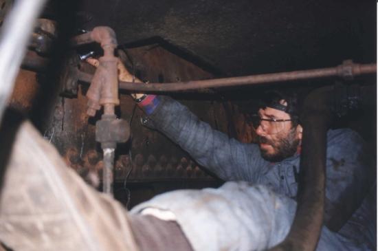
3. Measuring the Backhead Thickness: The part of the backhead below the cab floor has to be tested too. John Cox emulates Houdini as he gets that job done. Photo by Terry Thompson. 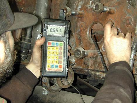
5. Robustly Built: Here's a sample reading. This spot was specified to be 9/16(=0.5625) in. thick but the reading of 0.661 suggests it was actually built to 11/16 in. Photo by Dale Birkholz. |
2. Making a UT Reading: John Cox makes a thickness measurement and Linda Vanderbeck records the reading. Photo by Dale Birkholz. 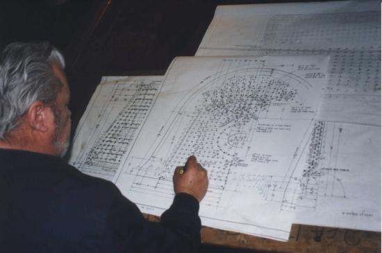
4. Recording a Reading: Don Wheeler records a reading for the backhead below the cab floor. Photo by Terry Thompson. |
VII. More Cleaning and Fixing
March-April: We took advantage of the fact that the boiler was empty to make a repair to the floor of the firebox and to clean out all the nooks and crannies.
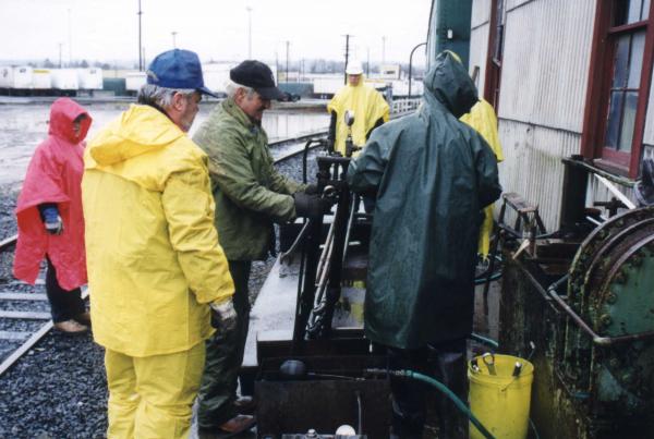
1. Preparing for the Wash: Terry Kimzey and Walt Eisenman discuss a washout plug while Charlie Harrison works on a blowdown valve. Photo by Dale Birkholz. 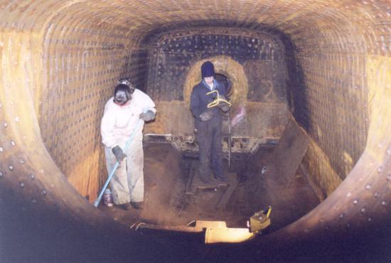
4. Firebox Clean-up: Linda Vanderbeck and David Thompson cleaning the firebox after its repairs. Photo by Terry Thompson. |
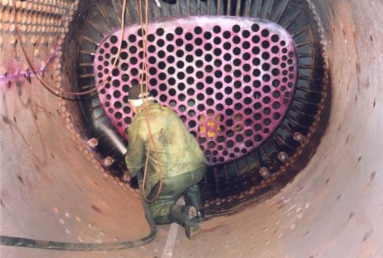
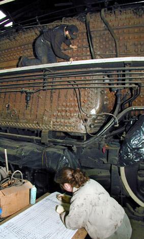
2. Behind the Ears: Walt Eisenman uses a firehose to washing around the outside of the combustion chamber in April, 2000. Dye penetrant is visible on the rear tube sheet and on the boiler walls. Photo by Terry Thompson 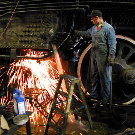
3. Washing the Sand from the Boiler: Bob Vanderbeck controls and keeps a close eye on the water coming out the mud-ring-level washout plug hole. Meanwhile, Jim Vanderbeck is inside the firebox welding the floor plates back down (we missed getting photos of the actual repairs). Photo by Dale Birkholz. |
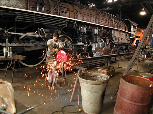
VIII. Swaging the New Tubes
With the inspection and repairs done, it's time to put the boiler back together. First to go in are the flue tubes. However, we're not reusing the old ones, we're installing new and these must be tapered in a process known as swaging at the firebox end before they can be installed. Only the larger diameter tubes--the one's that accommodate superheaters--need to be swaged. This we accomplish on June 10-11, 2000.
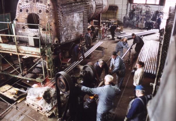
1. View of the Work Area: This view from the cab of the 700 shows an overview of the process. Flues come in the door of the roundhouse (in the background, right) to a staging area, then to the furnace on the left, then to the hammer in the foreground, finally into the crib to cool. That's OR&N 197 in the background. Photo by Terry Thompson. | |
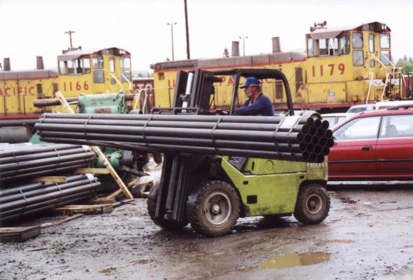
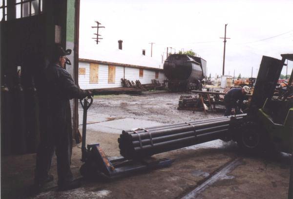
2. Bundle of New Tubes: Don Wheeler brings another bundle of flues on the fork truck. Photo by Terry Thompson. 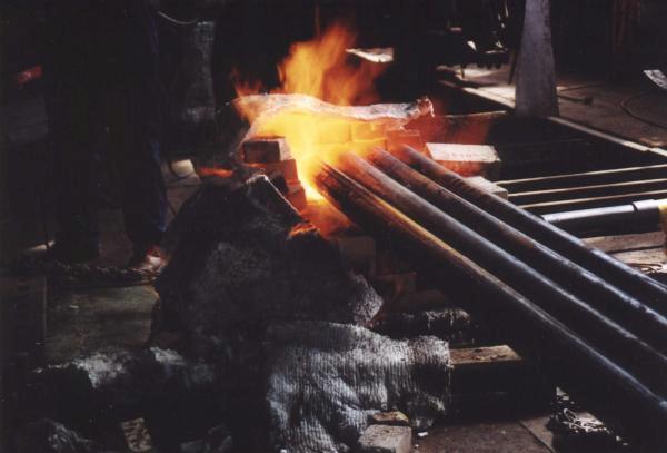
4. Into the Furnace: The flues are placed in this homemade furnace to be heated up so they are malleable enough for swaging. Photo by Terry Thompson. 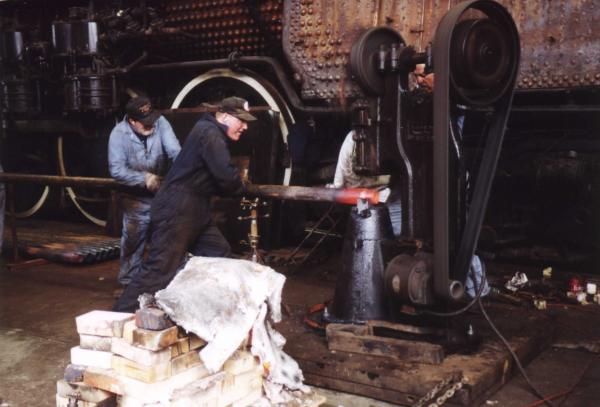
6. Loading a Flue into the Swaging Hammer: Charlie Harrison and Matt Baccitich push a hot flue into the "Little Giant 100 lb. Power Hammer" and rotate it on the swage die. Another person is pushing on the other end of the flue. Photo by Terry Thompson. 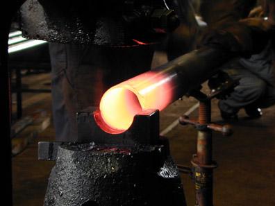
8. Wide: Flue just coming into the die. Photo by Dale Birkholz. 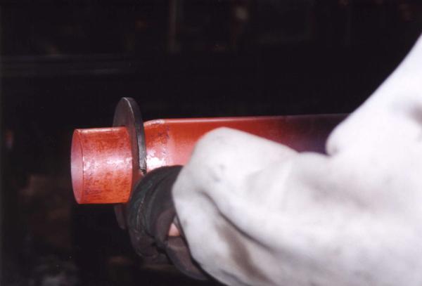
10. QC: The flue is checked for size by slipping a gauge over it. Photo by Terry Thompson. |
3. Staging: The bundle is then brought into the roundhouse. Photo by Terry Thompson. 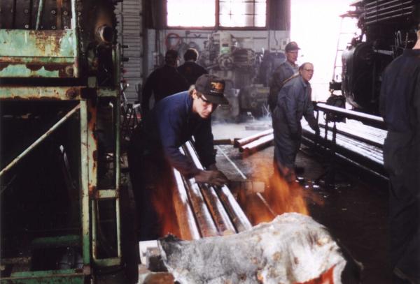
5. Heating the Flues: Jim Vanderbeck tends the fire and rotates the flues so they are heated
evenly. Photo by Terry Thompson. 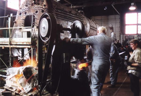
7. Swaging: Walt Eisenman controls the hammer with his foot, and through hand
signals, tells the crew when to advance the flue and when to retract.
Photo by Terry Thompson. 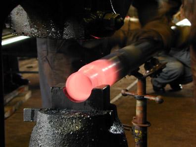
9. Narrow: This one is about done. Photo by Dale Birkholz. 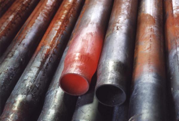
11. Cooling Off: A still-hot flue is added to the pile in the crib. Photo by Terry Thompson. |
IX. Stuffing the Flues
In March and April, we took advantage of the fact that the boiler was empty to make a repair to the floor of the firebox and to clean out all the nooks and crannies.
1. Measure Twice Cut Once: Walt Eisenman studies the layout of the flue sheet. The distance from front to back for each hole has been measured and recorded on this diagram. Photo by Dale Birkholz. 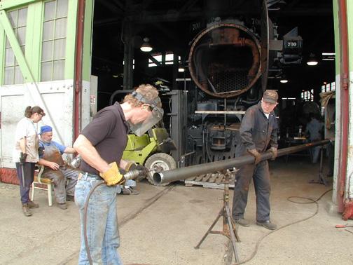
3. Smoothing the End. Photo by Dale Birkholz. 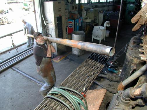
5. The Next Tube Comes in: Charlie Harrison hands up another a flue. Photo by Dale Birkholz. 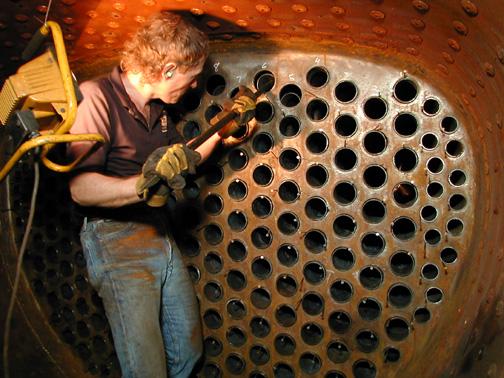
7. View from the Firebox: Jim Vanderbeck, now stationed at the opposite end of the boiler, guides one of the last flues into the rear tube sheet. Photo by Dale Birkholz. |
2. Making the Cut: John Cox cuts a flue to length. Photo by Dale Birkholz. 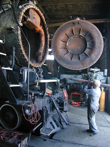
4. Ready for the Boiler: Walt Eisenman lifts up his end of a flue toward waiting parties in the firebox. Photo by Dale Birkholz. 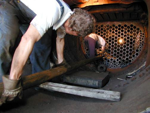
6. View from the Smokebox: Jim and Linda Vanderbeck guide a flue into the boiler. Photo by Dale Birkholz. 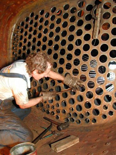
8. Preparing to Roll the Tube Ends: The firebox end of the boiler tubes, previous swaged to a narrower diameter, will be rolled to make a seal. Before that happens, they are "staked" in place using a nail with a flattened end to keep the flue from rotating during the rolling. Photo by Dale Birkholz. |
X. Pressure Testing the Superheaters
Before we put the superheaters back into the flues, we test each unit's integrity by running the pressure up to 800 psi and rapping on it sharply with hammers. This causes any weak spots to let go. This is done in late February while the boiler was being sandblasted so that we have time to make repairs or purchase new one while the other work is going on.
1. Setting up for a Test: Photo by Terry Thompson. 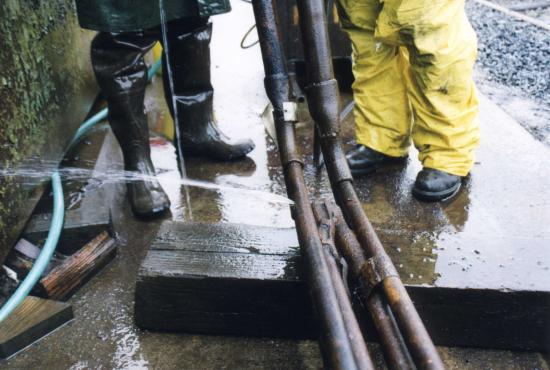
3. Bingo! Much as we don't like them to fail, it's far, far better here than in the engine. Photo by Terry Thompson. |
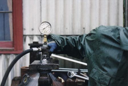
2. Building Pressure: Currently at 700 psi and climbing towards 800. Photo by Terry Thompson. 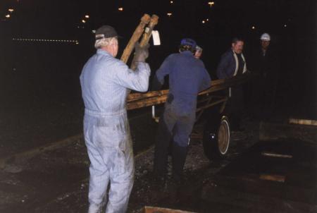
4. Carried Away: Superheater units are heavy! We need five people, four to lift and one to steady the cart, just to move each superheater unit to and from the testing area. Photo by Terry Thompson. |
XI. Putting Everything Back Together
There's still a lot left to do: rolling the tube's firebox ends, welding the tube's smokebox ends, stuffing the superheaters back into the flues, reassembling, putting all the new insulation onto the outside of the boiler and replacing the jacketing, to name a few. Unfortunately, we didn't take pictures, but there are shots from a test run on February 26, 2001 (just to prove we got through it okay). We ran the 700 about 30 miles over BNSF from Vancouver, WA, to Longview, WA, pulling a 4800 ton train.
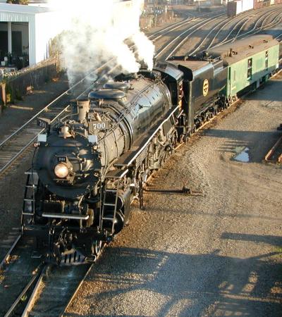
1. Under her Own Power: SP&S 700, fresh from her boiler rebuild, leaves Brooklyn yard en route to Vancouver on the day before her shake-down test. Photo by Dale Birkholz. |
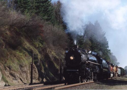
2. Northbound to Longview: Here the train approaches MP 111. You can see the protection power behind the tender. Photo by Frances Matlock. |