Turning the Drivers on the SP&S 700
When the driver tread is worn, there are three choices: buy new tires. remove the tires and turn them on a wheel lathe, or turn them in place with the tires on. The PRPA's machinist, Tom Weisner, chose the third way, which is shown below.
Getting the Drivers Off the Track (one axle at a time).
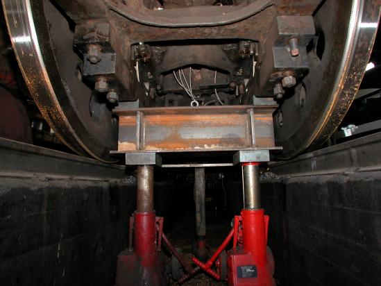
In this view from the pit beneath the SP&S 700, you see two jacks, each 75 ton lift / 100 ton hold, supporting an I-beam which in turn supports the axle on each side. At the time of the photo, the driver #4 had been partly turned, but was interrupted by our performance of a scheduled FRA hydro test. Between the hydro test itself and the draining of the boiler, there was unwanted water dripping and splashing around, which is why there are rust spots on the shiny driver tread. Photo by Terry Thompson.
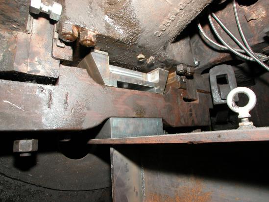
The binder has been lowered about an inch, allowing insertion of a trapezoidal spacer block that transmits the supporting force to jacking points on the axle housing without exerting a bending moment on the binder. Photo by Terry Thompson.
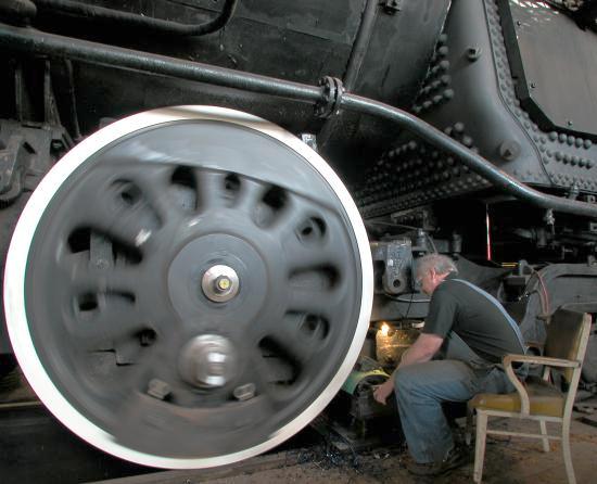
Rotating the Drivers
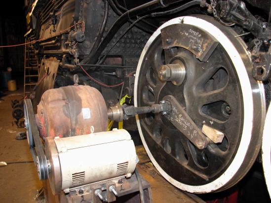
The driver is rotated with a 20 hp electric motor, a 195:1 reduction gear, a driveshaft, and a lever arm. The motor has been fitted with a flywheel to reduce stress on the drivetrain when the motor is shut off. With different size pulleys and belts, the cutting speed can set for either high speed or carbide tools. Notice the block of metal attached to the driver, currently at the top. With the rods off, the built-in counterweight, currently at the bottom, needs something added on the opposite side to balance its mass, so the driver will rotate at a uniform speed. So the block of metal could be called a counter-counterweight. Photo by Terry Thompson.
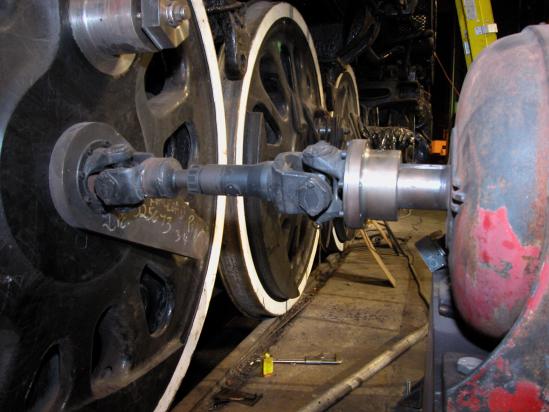
The driveshaft came off our VIA car, where it was originally driven off the axle to turn a generator that provided power and charged batteries while under way. Photo by Terry Thompson.
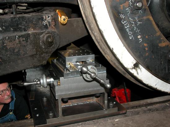
Building Lathe Parts
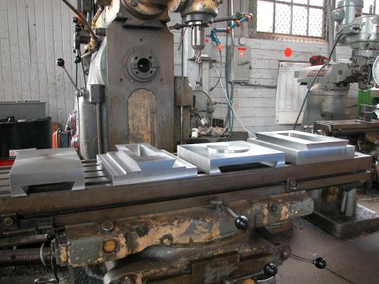
Machinist Tom Weisner designed and built the parts shown below which, when put together, provide compound and cross-feed controls to position the cutting tool. Photo by Terry Thompson.
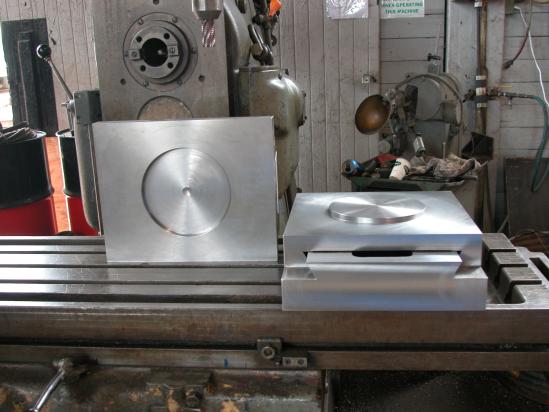
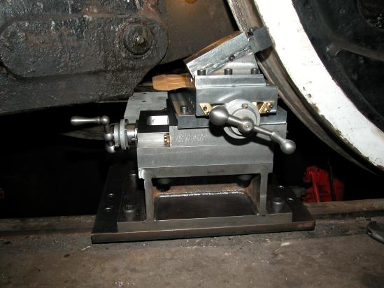
Another view showing how parts fit together. The constituent parts are designed so they can work on both sides of the locomotive and on the leading or trailing edge of the driver. Photo by Terry Thompson.
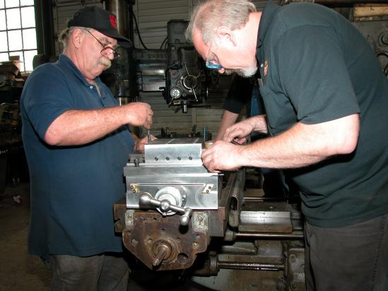
Roy Jones (left) and Tom Weisner fastening the parts together. Photo by Terry Thompson.
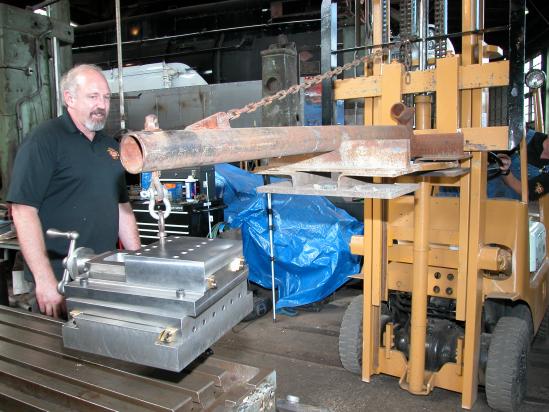
Tom watches while Dale Birkholz backs up the forklift, taking the just-assembled device over to the locomotive. Photo by Terry Thompson.
Dale Birkholz is down in the pit to help Tom fasten it to the plate across the tracks. Photo by Terry Thompson.
With the addition of the tool holder and a cutting tool in place, Tom is ready to make the very first cut and test his design. Photo by Terry Thompson.
Removing material
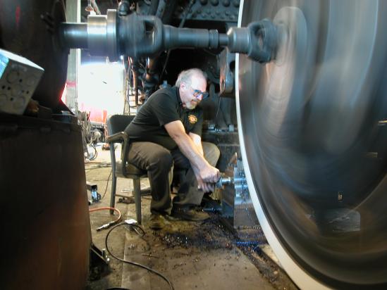
Ok, it's working!. Tom begins removing metal from driver #4 on the engineer's side. He started on the #4 drivers because they appeared to need the most material removed and would therefore set the size for the others. Photo by Terry Thompson.
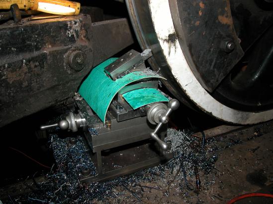
With the tread surface finished, just starting to work on the flange. The green material is to keep shavings out of the threads on the controls. Photo by Terry Thompson.
Tom now working on the fireman's side. Photo by Terry Thompson.