Turning the Drivers, Part 2.
Attaching the Counter-Counterweights.
Each driver is counterweighted to balance the rods attached to it and its own crankpin. The 4-8-4 configuration has the same size counterweights (at least to the eye) on the #1 and #4 drivers and differing sizes on the #2 and #3 drivers. That's because the amount of rod weight they are countering differs. The #1 and #4 drivers have just one rod, the #3 has two rods, and #2 has two rods plus the main rod plus a much larger crankpin.
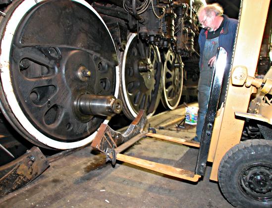
Tom Weisner takes a moment to think over the process for attaching the weights to the #2 driver. As you can see, the counterweight on this driver is enormous, covering almost the top half of the driver. In the background to the right, note the smaller size of #3's counterweight (sitting at about 4 o'clock) and #4's (sitting at about 6 o'clock). Also, note the much larger crankpin on #2. Photo by Terry Thompson.
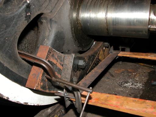
The attached weights were used in different combinations for #3 and #4. Number 2 will need them all and more. Photo by Terry Thompson.
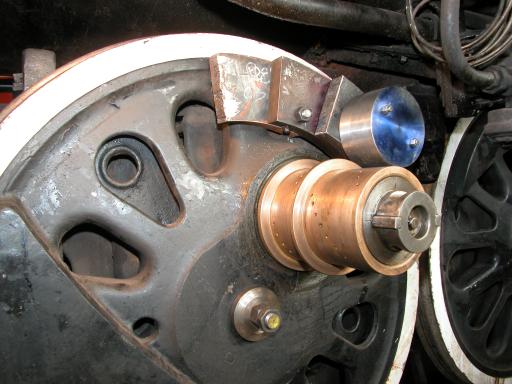
Here's the final weighting for #2. Besides the attached weights, the bearing has been slipped onto the crankpin. Photo by Terry Thompson.
Driveshaft
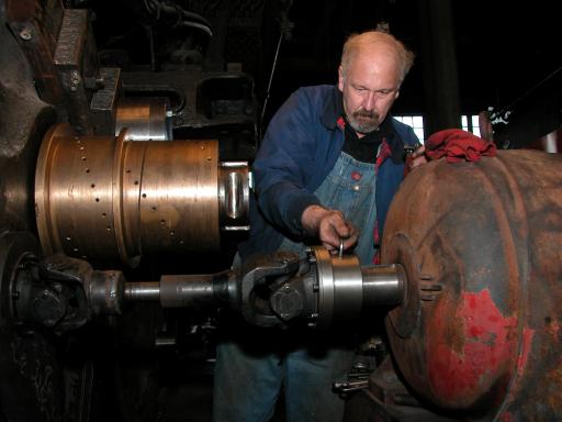
The above photos were taken on the fireman's side (left side). Now we're on the engineer's side where the drive shaft is attached to the #2 driver. Tom is finishing the attachment for this driver. The driveshaft was described in Part 1. Photo by Terry Thompson.
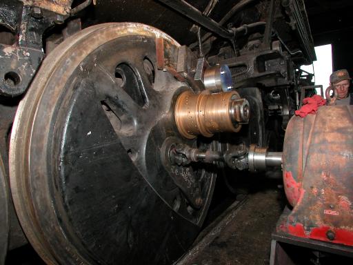
A wider view. The large housing on the right is the 195:1 reduction gear. Photo by Terry Thompson.
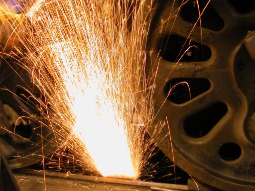
A worker in the pit is smoothing the inside of the rail prior to attachment of the heavy plate that spans the rails. Photo by Terry Thompson.